
How to Integrate an Automated Parts Cleaning System into a Production Line: Loading, Cycle Time, Fixtures, Robot Cells, and Quality Traceability

Integrating an automated parts cleaning system into a production line is not simply about purchasing a cleaning machine. The key is to design loading and unloading, cycle time, fixtures, cleaning processes, robot cells, inspection data, and quality traceability as one connected manufacturing process. Only when cleaning capacity, material flow, and line takt time are aligned can the system reliably meet cleanliness, drying, and delivery requirements.
Applicable Scenarios
Automated cleaning systems are suitable for mass production environments where cleanliness requirements are clearly defined and part flow is stable. They are widely used in automotive powertrain, new energy vehicle drive systems, hydraulic components, die-cast parts, precision machined parts, and final cleaning before assembly.
Typical applications include motor housings, transmission housings, valve bodies, pump bodies, gears, shafts, crankshafts, engine blocks, cylinder heads, aluminum die-cast structural parts, and battery tray connection parts. Automation becomes especially valuable when the cleaning system must connect with machining centers, deburring stations, leak testing machines, assembly lines, robotic handling systems, or automated storage systems.
Scenarios Where Caution Is Needed
If part variants change frequently, drawings and contaminants are not stable, or the cleanliness specification has not yet been defined, it is risky to plan a fully automated line immediately. Sample cleaning trials, fixture accessibility reviews, and cycle time simulations should be completed first.
For very small batches, highly mixed production, high manual rework rates, or unstable incoming part conditions, the highest level of automation may not be the best starting point. A more robust approach may involve quick-change fixtures, recipe management, semi-automatic loading, or a flexible robot cell, with automation increased step by step.
Typical Parts and Contaminants
Automated parts cleaning systems commonly handle:
New energy motor housings, reducer housings, inverter cooling plates
Transmission housings, gears, shafts, valve bodies, pump bodies
Engine blocks, cylinder heads, crankshafts, connecting rods
Aluminum die-cast parts, hydraulic blocks, oil circuit plates, aerospace precision structures
Machined parts requiring final cleaning before assembly
Common contaminants include chips, grinding dust, oil, emulsion, residual liquid, particles, burrs, oxides, release agents, anti-rust oil, and secondary contamination during handling. For internal holes, cross-drilled holes, blind holes, and complex cavities, contaminants are often trapped inside channels, shoulders, threaded holes, or fixture-shielded areas rather than simply sitting on the surface.
How to Choose Loading and Unloading Methods
The loading and unloading method is usually determined by part weight, takt time, positioning accuracy, upstream and downstream interfaces, and investment budget.
Manual loading is suitable for small to medium batches, lightweight parts, and projects still in process validation. It requires lower investment, but cycle time stability, traceability consistency, and labor intensity must be evaluated carefully.
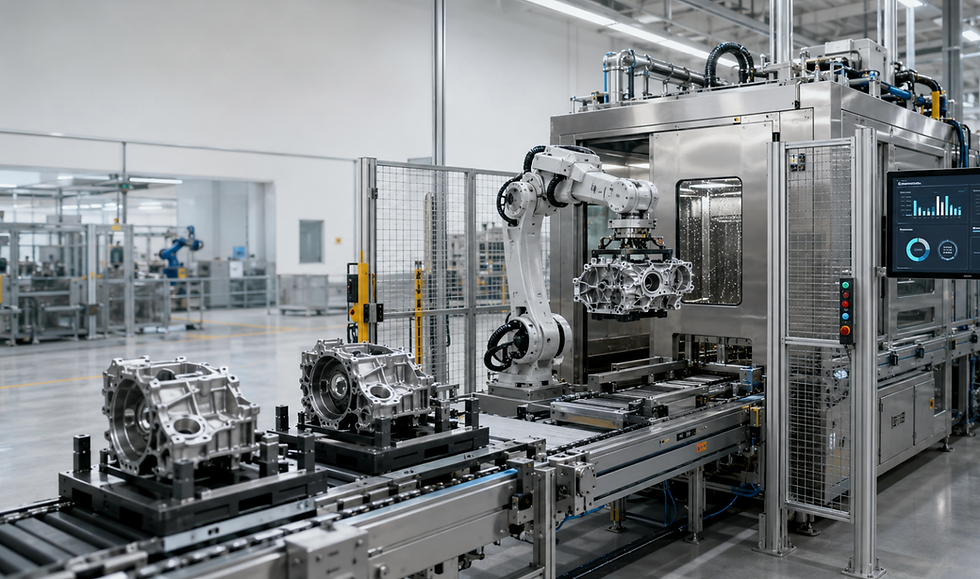
Automatic conveyor loading is suitable for stable part families, defined takt times, and standardized part orientation. Common solutions include roller conveyors, chain conveyors, pallet lines, return loops, and buffer sections. The advantage is stable flow and easier connection with machining, inspection, and assembly processes.
Robot loading is suitable for heavy parts, complex orientations, multi-machine connections, or flexible production. Robots can pick, turn, scan, place parts into fixtures, unload, transfer, and sort abnormal parts, provided that grippers, positioning references, and safety protection are well designed.
Cycle Time Matching Is More Than Cleaning Time
Cycle time matching should be based on the complete operating cycle, not only the spraying or ultrasonic cleaning time inside the chamber. A real cycle usually includes loading, scanning, positioning, clamping, cleaning, rinsing, draining, drying, cooling, unloading, buffering, and abnormal handling.
For example, if a machining line outputs one part every 45 seconds while the cleaning process requires 120 seconds, the project is not necessarily impossible. Engineers may use parallel stations, dual fixtures, continuous through-feed structures, buffer sections, or alternating robot loading to match the line. Conversely, if equipment is selected only by theoretical cleaning time, the site may face cleaning machine waiting, upstream blockage, or downstream starvation.
Fixture Design Determines Cleaning Accessibility
A fixture is not just a part holder. It directly affects spray coverage, cavity draining, drying performance, and cleanliness inspection results. A good cleaning fixture must meet requirements for positioning, load bearing, clearance, drainage, and maintainability.
During fixture design, the first question should be whether critical contamination areas are exposed, such as oil channels, blind holes, threaded holes, gear roots, shaft shoulders, housing cavities, and deep die-cast cavities. Clamping points must not block nozzle paths, pallet structures must not create liquid traps, and materials must withstand cleaning chemistry, temperature, and long-term cyclic impact.
For multi-variant projects, quick-change fixtures, adjustable locating blocks, ID-code binding, and recipe management can allow the equipment to switch cleaning paths, pressure, time, and drying methods automatically according to part type.
How to Integrate Robot Cleaning Cells
Robot cells are commonly used for complex workpieces, high-pressure deburring, targeted internal cleaning, flexible mixed production, and heavy-duty handling. A robot may carry a spray lance, gripper, vision system, scanner, or blow-off tool, and it can be combined with fixed spray stations, rotary tables, filtration systems, and safety fencing.
The core question is not whether a robot is installed, but whether the path, nozzle posture, distance, angle, and repeatability can cover the target contamination zones.
For parts with defined holes and burr locations, offline programming, sample validation, and spray coverage testing should be used to confirm the path. For high-pressure cleaning, splash control, door interlocks, pressure release, and maintenance access must also be evaluated.
How to Design the Process Combination
In an automated production line, cleaning is usually a combination of processes rather than a single method.
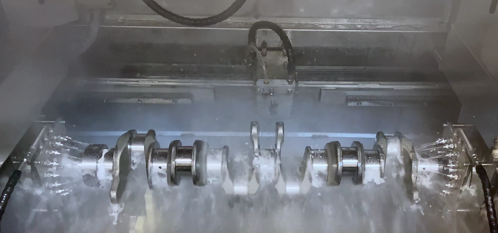
Spray cleaning is suitable for surface oil, loose particles, and high-volume through-feed cleaning. Ultrasonic cleaning is useful for complex surfaces, fine particles, and shadowed areas, but material compatibility, frequency, basket shielding, and rinsing capacity must be considered. High-pressure cleaning is suitable for targeted deburring, deep holes, and cross holes, but pressure, nozzle angle, and part damage risk must be controlled.
Immersion and rotation help with air release, agitation, and full-surface contact. Rinsing reduces detergent residue and secondary contamination. Hot-air drying is suitable for more open structures, while vacuum drying is better for blind holes, deep cavities, and parts sensitive to residual liquid.
A good process combination should be derived from contaminants and cleanliness targets, not from a list of available machine functions.
Key Parameter Framework
During purchasing and technical review, at least the following parameters should be defined:
Part size, weight, material, and critical cleaning zones
Contaminant type, contamination load, and upstream process source
Target takt time, shifts, daily output, and buffer requirement
Spray pressure, flow rate, nozzle layout, and coverage
High-pressure deburring pressure, nozzle distance, angle, and exposure time
Cleaning temperature, detergent type, concentration, and replenishment method
Filtration rating, filtration flow, differential pressure monitoring, and filter maintenance cycle
Number of rinsing stages, water quality control, and anti-recontamination measures
Drying method, residual liquid risk, and discharge temperature
Automation interfaces, communication protocol, scanning method, and data recording requirement
Specific values should be confirmed through sample trials, especially high-pressure parameters, filtration rating, drying time, and mixed-production cycle time.
How to Design Quality Traceability
Quality traceability should be designed from the beginning of the project, not added as software after equipment delivery. A traceable cleaning system typically records part type, batch, pallet ID, scan data, process recipe, cleaning pressure, temperature, time, filtration status, alarms, maintenance records, and inspection results.
For automotive technical cleanliness projects, particle analysis, gravimetric analysis, microscopic analysis, and extraction records may be aligned with common methods such as ISO 16232 and VDA 19. Traceability is not only about generating reports. More importantly, when a cleanliness deviation occurs, it helps identify whether the root cause is upstream contamination change, nozzle blockage, filtration failure, fixture shielding, rinse contamination, or insufficient drying.
GRT Solution Perspective
When planning automated parts cleaning projects, GRT typically starts with part drawings, contaminants, cleanliness requirements, takt time, upstream and downstream interfaces, and acceptance criteria instead of directly recommending a standard machine model.
During the proposal stage, GRT evaluates part orientation, fixture accessibility, cleaning path, filtration capacity, drying risk, and automation interfaces. During validation, sample trials are used to confirm cleaning effect, residual liquid risk, and cycle time boundaries. During delivery, the focus extends to electrical standards, safety protection, data recording, FAT, SAT, maintainability, and overseas project support.
This approach is especially relevant for industrial projects with defined cleanliness targets, complex line integration, and long-term stable operation requirements.
Case
A European new energy vehicle component project needed to integrate an e-drive housing cleaning system between machining and assembly. The customer faced aluminum chips, emulsion, and local residual liquid inside the housing cavities. Manual handling caused unstable cycle time, and the quality team required batch-level traceability of cleaning parameters.
The solution used a pallet conveyor with robotic loading and unloading. The cleaning section combined targeted spray cleaning, local high-pressure cleaning, multi-stage rinsing, and vacuum drying. The fixture design avoided critical holes and included a defined drainage angle.
The system linked part type and process recipe through scanning and recorded pressure, temperature, time, filtration status, and alarm data.
The result was that the cleaning cycle matched the main production line, residual liquid issues were significantly reduced, and the quality team could trace the cleaning process by batch. Specific cleanliness limits and output data remain confidential, but the engineering logic is typical for similar projects.
FAQ
1. Is an automated cleaning line always better than a standalone cleaning machine?No. For stable mass production, defined takt time, and high traceability requirements, an automated line is more suitable. For small batches, changing parts, or early validation, a standalone or semi-automatic solution may be more practical.
2. What risk is most often underestimated during line integration?Loading cycle time, fixture shielding, buffer capacity, and abnormal handling are often underestimated. Many projects fail not because of the cleaning process itself, but because material flow and interfaces are not designed properly.
3. Is robot cleaning suitable for all complex parts?No. Robot cleaning is suitable for targeted cleaning, changing orientations, or flexible part switching. If the part geometry is simple and takt time is extremely high, a continuous through-feed cleaning line may be more economical.
4. Should fixture design be linked with cleanliness validation?Yes. Fixtures influence spray coverage, particle retention, and drainage. If a fixture blocks critical areas, even high equipment parameters may not pass cleanliness inspection.
5. What data should be recorded for quality traceability?Recommended data includes part ID, batch, recipe, pressure, temperature, time, filtration status, alarms, maintenance records, and inspection results. High-requirement projects should also link the data with cleanliness reports.
6. What if the cleaning cycle cannot match the production line takt time?Possible solutions include parallel stations, dual fixtures, buffer sections, alternating robot loading, shorter non-cleaning steps, or an adjusted process combination. These must be confirmed through cycle simulation and sample validation.
7. What information should be provided to the supplier at the early project stage?Part drawings, material, weight, contaminants, upstream process, cleanliness specification, production takt time, plant layout, upstream and downstream interfaces, and acceptance method should be provided.
Conclusion
If you are planning an automated parts cleaning system, it is useful to first prepare part drawings, contaminant information, cleanliness targets, takt time, loading concept, and traceability requirements.
Based on these inputs, GRT can help evaluate fixtures, process combinations, robot cells, and line integration concepts, and provide technical recommendations closer to real production conditions.
Comments